This account was written by Brian Carter and included in a submission prepared by Phil Hodgson, a teacher at Evenwood C. of E. Controlled School, which formed part of the school’s submission as its contribution to a “Coal Mining Project” by Durham County Council Education Department, in 1991. Brian was employed as a laboratory assistant then site chemist by Randolph Coke & Chemical Co. Ltd. between 1968 and 1984.
- INTRODUCTION
In the early days, the carbonisation of coal was undertaken to manufacture coal gas for domestic and industrial use. The coke was produced for use in the steel industry. However, the value of various products from the process could change and with it, the economics of the operation. For example:
- Natural gas reduced the viability of coal gas production
- The demise of the steel industry and increased air pollution control reduced the need for metallurgical coke and increased the need for domestic coke.
- The value of the chemical by-products was constantly changing depending upon demand.
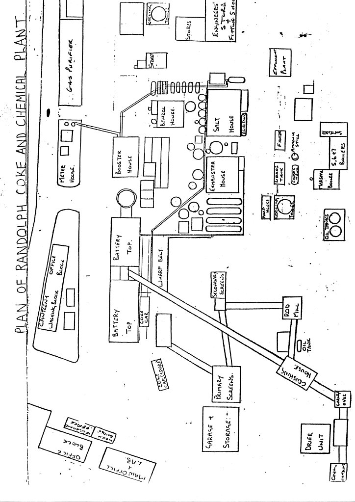
The following is a brief, simplified description of the production of coke and by-product recovery. The sequence of events is shown in the flowchart (figure 1) and a simplified plan of Randolph Coke and Chemical C. Ltd. Plant is shown (figure 2).
- COAL PREPARATION
Coal was stocked in the stockyard in heaps with material of similar quality being stocked together. The coals of different quality were transported to the coal blending plant where each was placed in individual hoppers. These coals were then run from the hoppers at specific rates to achieve the correct blend depending upon production requirements. The coals were mixed thoroughly as they went through the, “change-over” building and the coal crusher. At the coal crusher, coke breeze was added after going through the rod mill to adjust the strength of coke required. In later years, the addition of petroleum coke fines, (a by-product of oil refining) was also used to this end. The complete blend, after leaving the coal crusher, would be reduced to at least 80% less than 5mm. and transported by conveyor belt to the storage hopper on the coke battery (see photo 9). This was capable of storing approx. 500 tonnes of coal, about 1 day’s production needs.
- COKE PRODUCTION
Coal was loaded to each oven from a, “larry car” carrying 4 hoppers which had been filled from the main storage hopper. This was enough for 1 oven (see photo 10). Loading was done through 4 holes in the top of each oven in a sequence that allowed for even filling of the oven. Upon completion of loading, lids were then replaced on the holes and sealed leaving the oven airtight. Depending upon the coke required, the temperature of the oven would be maintained at 1200-1300 degrees C. in the walls and up to 1350 degrees C. in the centre of the carbonising coal. During an average working day, an oven would be pushed and recharged approximately every 30-40 minutes. While carbonisation was occurring, the by-products were removed from the oven along pipes to the reclamation plant.
Upon completion of carbonisation, the loading lids were released and the doors at either end of the oven removed (see photo 11). The coke produced would then be pushed out by a machine called, “the ram” from the oven into the coke car (see photo 12) and transported under the quenching tower where the hot coke was sprayed to cool it down. When cooling was completed, the coke was transferred to the wharf and released onto conveyor belts to transport it to the coke cutter where it was reduced in size and then to the screening plant to be sorted into approximate size ranges. Randolph produced up to 6 sizes classed as:
- Large 60+mm
- Trebles 60mmx40mm
- Doubles 40mmx20mm
- Beans 30mmx10mm
- Breeze -10mm
4. BY-PRODUCT RECLAMATION
4.1. COAL TAR
The tar was removed from the ovens as a tar/liquor mix through the main pipes assisted by a liquor spray to remove it and the coal gas produced flowed from the ovens through the same pipe. The bulk of the tar is in the liquor and was removed in the tar/liquor trap from the main to the tar/liquor decanting tank where the tar and liquor are separated and transferred to their respective storage tanks.
The gas continues along the main, through a series of cooling towers after which it was boosted by pumps in the exhauster house through a de-tarrer to remove remaining tar before the gas continues its progress to further by-product recovery.
The liquor storage tank only holds a limited amount, primarily to be used in the liquor spray mentioned earlier. The remainder was passed through ammonia still, which recovered waste ammonia that was directed to the sulphate ammonia plant (see next section). The liquor was then transferred through a filter bed to remove solids then to a biological effluent plant to treat the effluent before disposal.
4.2. SULPHATE OF AMMONIA
Coal gas contains considerable amounts of ammonia. The gas plus ammonia removed from the liquor is brought into contact with sulphuric acid until an ammonium sulphate slurry is formed. At this point, the slurry is transferred to a centrifuge where the solid sulphate of ammonia was removed and the sulphuric acid recovered. The wet “salt” was then dried and bagged. The final product was then removed by a buyer and further purified for principal use as a fertilizer.
4.3. CRUDE BENZOLE
The crude benzole was recovered from the coal gas by what was called the, “contact process”. After the sulphate of ammonia process, the gas was cooled through the final set of coolers and was then passed upwards through the scrubbers. These were tall, metal, cylindrical, sealed structures filled with wooden perforated baffles. As the gas flowed upwards, hot absorbing oil was sprayed down onto the gas and baffles (originally creosote oil but later aliphatic oils). The fine spray of droplets absorbed the crude benzole from the gas (see photo 13).
The absorbing oil. Saturated with crude benzole, was then passed to the large stills where the crude benzole was removed by distillation and condensation before being transferred to storage. The new cleaned absorbing oil was re-circulated for re-use. As no process is perfect, this oil did gradually become saturated with the heavier products of crude benzole and was sold for reclamation.
The crude benzole was sold for purification to recover the cocktail of chemicals in the mixture, principally benzene, xylene (o, m and p-xylen) with numerous other components.
At this stage, the naphthalene was removed from the gas but was not a commercial proposition and was therefore disposed of as a waste material.
4.4. COAL GAS
After all these processes, there was still one final clean up procedure to be carried out on the gas – that was to remove the hydrogen sulphide. This involved passing the gas through large containers containing what was popularly called, “bog ore” but was principally an iron oxide material. As the bog ore became saturated forming iron sulphide, it was sold off for recovery of the sulphur.
As stated at the beginning, the coal gas used to be sold off for general consumption however the users at the close of the coke works were private companies – Evenwood Engineering and Potters Ballontini at West Auckland. The remainder of the gas was used to:
- Raise steam in the boiler plant to operate the various steam driven pumps around the works
- Provide under firing for the coke ovens to maintain temperatures.
The remainder was burnt as waste.
- ADDITIONAL DETAIL AND TECHNICAL INFORMATION
- COKE OVENS
The coke ovens consisted of 2 batteries of 15 and 11 ovens. The design of the ovens showed a tapered shape with the end of the coke car side of the battery wider than the other in order to assist pushing. The “walls” of the oven were actually hollow into which 27 jets protruded through which gas was fed to heat the ovens. These hollow walls were alternatively heated and then operated as flues. Control of the temperature conditions of the ovens was performed by:
- Altering air flows to the walls
- Altering the rate of gas to the wall by nozzle size and gas aperture
- Adjusting stack draught
Checking the temperature of the walls was performed using an optical pyrometer by:
- Taking full cross profiles usually one per shift
- Taking the temperature of 2 flues per shift, the 7th either side 2 hours before pushing
These temperatures were taken when the walls of gas were acting as flues, (an example of a daily report sheet is provided).
- COOLING TOWER
The vast amounts of water used for quenching were not re-usable as waste steam due to the presence of particulate matter. The large cloud of steam generated would have required fairly sophisticated equipment to remove the material which, with the acid nature of the steam, would have caused heavy abrasive corrosion of plant machinery.
- COOLING TOWERS AND BOILER PLANT
Continuous monitoring of the water quality in the cooling towers and the 4 boilers was necessary to ensure efficient operation. This principally, involved checking the hardness, pH and alkalinity of the water. In the cooling system, an emphasis was also made on the treatment of the water to prevent algal growth (which would have reduced the efficiency of the units) and also the prevention of corrosion.
- BIOLOGICAL EFFLUENT PLANT
This was installed in 1977 to treat the effluent before disposal off site. It operated on the principle of “feeding” the effluent to a vast tank of bacteria, which was designed to remove the pollutants:
- Sulphide
- Cyanide
- Phenols
- Ammonia
The process reduced the permanganate value and chemical oxygen deficiency, should the effluent find its way into a river source.
- COAL DRYER
A coal dryer was installed in an attempt to increase production of coke and by-products. The theory was to reduce the moisture content of the coal charged from 7-9% w/w to approx. 5% w/w. This would mean more of the material in each oven would be coal and not water. Unfortunately, the drawback was that as the coal was drier, it was prone to ignite easier as it was charged to the oven therefore causing risk of flash back through the charging hole. The idea has been used at the British Steel Redcar coke works however at this plant the coal is loaded by pipeline feed and is not exposed to the atmosphere.
FIGURES
1. Flowchart of the Process
2. Simplified Plan of the Coke Works & Chemical Plant at Randolph, Evenwood